納米多孔金屬材料具有納米尺度的三維雙連續(xù)固體-空隙結(jié)構(gòu),其比表面積大、孔隙率高和孔結(jié)構(gòu)多樣的特點使其具有獨特的物理、化學(xué)和機械性能,在催化[1,2]、傳感[3~5]、
污水處理[6,7]以及超級電容器[8]等領(lǐng)域得到了廣泛的應(yīng)用
制備納米多孔金屬材料的方法,如金屬有機沉積法和模板法等的操作難度大,且耗時較長[9,10]
與這些方法相比,化學(xué)與
電化學(xué)脫合金法的操作簡單且可控性強等,可用于選擇性溶解活性組分制備納米多孔金屬
目前,用電化學(xué)脫合金法能選擇性溶解Au-Ag單相合金中的金屬Ag制備納米多孔Au[11~14],還能制備納米多孔Pt[15~17]、Ag[18,19]和Pd[20]等貴金屬納米多孔材料
但是,貴金屬的價格高昂,而Cu[21]和Ni[22,23]等非貴金屬體系納米多孔材料的價格低廉、易于回收且環(huán)境友好
其中用Cu-Al[24]、Cu-Zn[25]、Ti-Cu[26]等非貴金屬體系脫合金處理制備的納米多孔Cu備受關(guān)注
Xu等[27]報道,納米多孔Cu對有機小分子的氧化具有優(yōu)異的催化活性和穩(wěn)定性
這意味著,過渡族金屬納米多孔材料在燃料電池和電化學(xué)等領(lǐng)域有極大的應(yīng)用潛力
Fe是價格便宜、儲備豐富的過渡金屬元素,可用于制備具有催化性能的納米多孔材料[28~31]
Fe元素優(yōu)異的電導(dǎo)性,可使電子從催化劑表面快速轉(zhuǎn)移到支撐電極
同時,由Al、Fe等金屬電極、電解質(zhì)和空氣電極組成的金屬-空氣電池具有能量密度高、成本低和結(jié)構(gòu)緊湊等特點,引起了極大的關(guān)注[32]
而對于該電池體系中的電極材料,三維多孔結(jié)構(gòu)的催化劑負荷高、催化劑和電解質(zhì)之間的接觸面積大[33],能顯著提高其催化反應(yīng)活性和反應(yīng)動力學(xué)
因此,低成本、高自然豐度且環(huán)境友好的納米多孔Fe可有效增強電化學(xué)氧化還原反應(yīng),作為金屬-空氣電池體系中的電極材料具有巨大的應(yīng)用潛力
鑒于此,本文使用在773~833 K熱處理的Fe76Si9B5P10非晶合金為前驅(qū)體,用脫合金法在H2SO4溶液中自然脫合金制備納米多孔Fe-Si-B-P結(jié)構(gòu),在堿性電解質(zhì)中研究納米多孔Fe-Si-B-P的電化學(xué)性能并探討其脫合金機制和高電化學(xué)活性的原因
1 實驗方法1.1 納米多孔Fe-Si-B-P條帶的制備
將實驗用純度高于99.9%的Fe、Si、B和Fe-P中間合金在高純氬氣氛中進行電弧熔煉,制備出設(shè)計成分為Fe76Si9B5P10的合金錠,然后采用單輥急冷甩帶法制備出厚度約為20 μm、寬度約5 mm的非晶合金條帶,將多份Fe76Si9B5P10非晶合金條帶分別在不同溫度熱處理600 s
最后將這些在不同溫度熱處理的Fe76Si9B5P10合金條帶分組,將其分別在不同濃度的H2SO4溶液中沉浸不同時間(600~3600 s)完成脫合金處理,得到納米多孔Fe-Si-B-P條帶
1.2 性能表征
用Cu Kα激發(fā)的X射線衍射(XRD,Rigaku)和透射電子顯微鏡(TEM,JEOL 2100F)表征樣品的相結(jié)構(gòu)
在氬氣流下用差示掃描量熱儀(DSC,TA)分析非晶合金樣品的熱穩(wěn)定性,升溫速率為0.33 K/s
用掃描電子顯微鏡(SEM,QUANTA FEG 250)觀察脫合金樣品的表面形貌和微觀結(jié)構(gòu)(加速電壓為20 kV),并用能量色散X射線能譜儀(EDS)分析脫合金樣品表面的元素
使用Nanomeasure軟件測量分析納米多孔的孔徑
在標準三電極系統(tǒng)下用PARSTAT-4000電化學(xué)工作站進行CV測試
在6 mol/L KOH溶液中,工作電極為在773 K熱處理并在0.05 mol/L H2SO4溶液中脫合金3600 s的納米多孔FeSiBP條帶,Pt為對電極,飽和甘汞電極為參比電極
同時,對未處理的Fe76Si9B10P5非晶條帶進行對比研究
CV測試中電位區(qū)間設(shè)置為-1.6~0 V,掃描速率分別為10、30、50、70、90和110 mV/s
2 結(jié)果和討論2.1 Fe76Si9B5P10 非晶合金的熱穩(wěn)定性
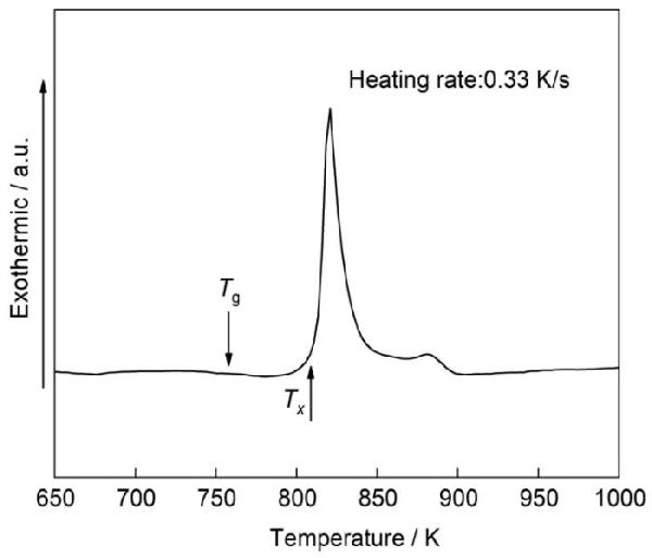
圖1給出了Fe76Si9B5P10非晶合金的DSC曲線
可以看出,F(xiàn)e76Si9B5P10非晶合金的玻璃化溫度Tg為790 K,結(jié)晶溫度Tx為803 K
圖1
圖1Fe76Si9B10P5非晶合金的DSC曲線
Fig.1DSC curve of Fe76Si9B10P5 amorphous alloy
2.2 Fe76Si9B5P10 非晶合金的微觀結(jié)構(gòu)
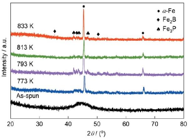
為了得到納米晶結(jié)構(gòu),將Fe76Si9B5P10非晶合金條帶分別在773、793、813和833 K進行了熱處理
圖2和圖3分別給出了熱處理前后Fe76Si9B5P10合金條帶的XRD譜、TEM照片及相應(yīng)的選區(qū)衍射譜(SADs)
如圖2和圖3a、b所示,在Fe76Si9B5P10合金條帶的XRD譜和選區(qū)衍射譜中只有一個彌散峰或彌散環(huán),表明是典型無特征結(jié)構(gòu)的非晶態(tài)
而在773~833 K熱處理后的XRD譜中的45.3°和65.9°處出現(xiàn)了明顯的衍射峰,分別對應(yīng)α-Fe相的(110)和(200)晶面,表明非晶合金發(fā)生了晶化,主要析出了α-Fe相
同時,在XRD譜中還有多個來源于Fe2B相和Fe3P相的衍射峰
圖3b給出了在773 K熱處理的Fe76Si9B5P10前驅(qū)體條帶的TEM照片和SAD圖
可以看出,平均尺寸約為155 nm的晶粒均勻分布,圖中的衍射環(huán)可標定為α-Fe相的(101)、(105)和(021)晶面,及Fe2B相的(110)、(002)和(211)晶面
根據(jù)XRD譜和TEM照片,F(xiàn)e76Si9B5P10前驅(qū)體合金在熱處理后發(fā)生了晶化
圖2
圖2Fe76Si9B10P5非晶合金及其在不同溫度熱處理后的XRD譜
Fig.2XRD patterns of Fe76Si9B10P5 amorphous alloy and its crystallized counterparts after annealing at different temperatures
圖3
圖3Fe76Si9B10P5非晶合金及其在773 K熱處理后的明場圖像和相應(yīng)的選區(qū)衍射圖
Fig.3Bright field images and corresponding selective area diffraction patterns of Fe76Si9B10P5 amorphous alloy (a) and its crystallized counterpart after annealing at 773 K (b)
2.3 脫合金后的納米多孔結(jié)構(gòu)
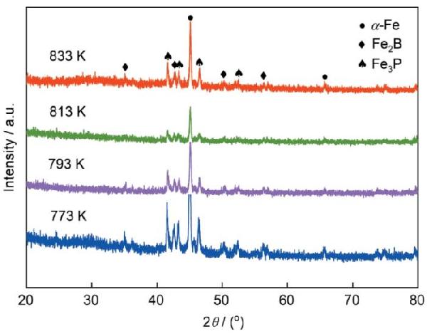
圖4給出了在不同溫度熱處理的Fe76Si9B10P5合金在0.05 mol/L H2SO4溶液中脫合金后的XRD譜
可以看出,在45.3°和65.9°處出現(xiàn)兩個來自α-Fe晶體相的衍射峰,表明脫合金處理后仍殘留部分α-Fe相
與熱處理后未脫合金的樣品相比,F(xiàn)e2B相和Fe3P相的相對衍射強度更強,表明α-Fe晶粒在 H2SO4溶液中發(fā)生部分優(yōu)先溶解
其原因是,α-Fe相和Fe2B相及Fe3P相之間的活潑性不同
圖4
圖4在不同溫度熱處理的Fe76Si9B10P5合金在0.05 mol/L H2SO4溶液中脫合金處理后的XRD譜
Fig.4XRD patterns of Fe76Si9B10P5 alloy annealed at different temperatures after dealloying in 0.05 mol/L H2SO4 solution
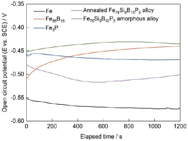
為了揭示脫合金機制,圖5給出了在0.05 mol/L H2SO4溶液中測試的α-Fe相、Fe-B相(Fe85B15)、Fe3P相和773 K熱處理Fe76Si9B10P5合金的開路電位(OCPs)與浸泡時間的關(guān)系曲線
所有樣品均在0.05 mol/L H2SO4溶液中發(fā)生活性溶解,但是其初始的開路電位不同
α-Fe相的穩(wěn)定開路電位為-0.57 V,遠低于浸泡1200 s后的Fe-B相(-0.44 V)、Fe3P相(-0.46 V)、熱處理Fe76Si9B10P5合金(-0.50 V)和Fe76Si9B10P5非晶合金(-0.43 V),表明α-Fe相在0.05 mol/L H2SO4溶液中具有最高的溶解活性
而存在于晶體合金中的Fe2B相表現(xiàn)出比Fe85B15更高的開路電位,因為Fe2B相中的B/Fe比率高于Fe85B15中的比率
即在0.05 mol/L H2SO4溶液中,α-Fe相和Fe2B相及Fe3P相之間存在明顯的電位差
各相之間活潑性的差異產(chǎn)生的微電偶使α-Fe晶粒優(yōu)先溶解,最終形成了納米多孔結(jié)構(gòu)
圖5
圖5純Fe、Fe85B15合金、Fe3P合金、Fe76Si9B10P5非晶合金和熱處理Fe76Si9B10P5合金在0.05 mol/L H2SO4溶液中的開路電位與浸泡時間的關(guān)系
Fig.5OCPs with immersion time of the high-purity Fe plate, Fe85B15 alloy, Fe3P alloy, as-spun Fe76Si9B10P5 amorphous alloy and annealed Fe76Si9B10P5 alloy in 0.05 mol/L H2SO4 solution
圖6給出了分別在773、793、813、833 K熱處理的Fe76Si9B5P10條帶在0.05 mol/L H2SO4溶液中脫合金處理3600 s后的表面微觀形貌
從圖6可見,F(xiàn)e76Si9B5P10合金表面形成了均勻的納米多孔結(jié)構(gòu)
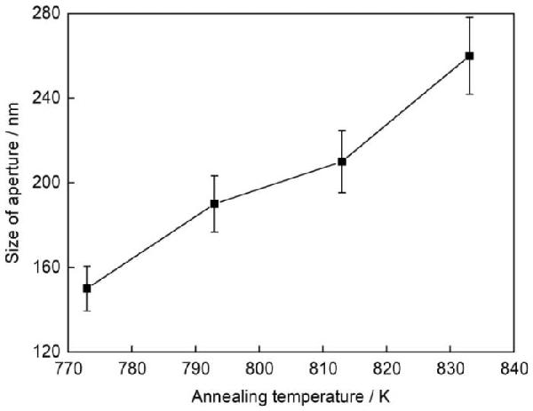
從圖7可見,隨著熱處理溫度的提高多孔孔徑的平均尺寸也從在773 K處理后的150 nm增大到在883 K處理后的260 nm
圖6a給出了在773 K熱處理后的Fe76Si9B5P10非晶合金的橫截面SEM照片
可以看出,在樣品的內(nèi)部已經(jīng)形成了納米多孔結(jié)構(gòu),即樣品經(jīng)3600 s脫合金處理后已經(jīng)完全多孔化
圖6
圖6Fe76Si9B10P5合金在773、793、813和833 K溫度熱處理后在0.05 mol/L H2SO4溶液中脫合金處理樣品的SEM照片,內(nèi)嵌圖片為橫截面SEM照片
Fig.6SEM morphologies of dealloyed Fe76Si9B10P5 alloy annealed at 773 K (a), 793 K (b), 813 K (c) and 833 K (d) in 0.05 mol/L H2SO4. Inset is an image of cross section after dealloying
圖7
圖7Fe76Si9B10P5合金在不同溫度熱處理后在0.05 mol/L H2SO4溶液中脫合金處理樣品的平均孔徑
Fig.7Aperture size of Fe76Si9B10P5 alloys annealed at different temperatures after dealloying in 0.05 mol/L H2SO4
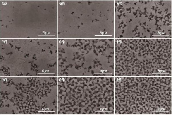
圖8給出了樣品在不同濃度的H2SO4溶液中完成脫合金處理后的表面形貌
在脫合金過程的初始階段部分α-Fe晶粒優(yōu)先溶解于0.005、0.01和0.05 mol/L H2SO4溶液中,然后附近的α-Fe晶粒發(fā)生陽極溶解使孔隙的數(shù)量不斷增加并逐漸相連,形成納米多孔結(jié)構(gòu)
同時,在0.05 mol/L H2SO4溶液中處理3600 s的條帶表面的孔隙均勻,而在其他濃度的H2SO4溶液中的樣品卻沒有形成均勻的孔隙
這表明,溶液的濃度越高則α-Fe晶粒的溶解速度越快,使孔隙的數(shù)量隨著時間的延長而增加
圖8
圖8在773 K熱處理的Fe76Si9B10P5合金分別在0.005、0.01和0.05 mol/L的H2SO4溶液中脫合金處理600、1800、3600 s后所得樣品的SEM照片
Fig.8SEM morphologies of Fe76Si9B10P5 alloys annealed at 773 K after dealloying in 0.005 mol/L (a), 0.01 mol/L (b), 0.05 mol/L (c) H2SO4 solutions for 600 s (a1~a3), 1800 s (b1~b3), 3600 s (c1~c3)
2.4 納米多孔結(jié)構(gòu)的電化學(xué)性能
圖9給出了脫合金后的納米多孔(NP FeSiBP)和Fe76Si9B10P5非晶合金(AM FeSiBP)在6 mol/L KOH溶液中掃描速率為50 mV/s時不同循環(huán)周期的CV曲線
從圖9a可見,AM FeSiBP的第一個循環(huán)周期內(nèi)分別在約-1.14 V(峰I)和-0.6 V(峰II)處出現(xiàn)氧化峰,其峰值電流密度分別為0.0020和0.0085 A/cm2,分別對應(yīng)Fe→Fe(OH)2和Fe(OH)2→FeOOH的氧化過程[33]
隨著循環(huán)次數(shù)的增加,在約-0.74 V處還出現(xiàn)了一個氧化峰,可能是非金屬元素氧化導(dǎo)致的電流上升
回掃描時分別在-1.20 V(峰III)和-1.33 V(峰IV)處出現(xiàn)還原峰,其峰值電流密度分別為-0.0037和-0.0051 A/cm2
隨著循環(huán)次數(shù)的增加氧化峰和還原峰的峰值電流密度逐漸增大,但是峰電位的變化較小
經(jīng)過10次電化學(xué)循環(huán)后,氧化峰Ⅱ和還原峰Ⅳ的峰值電流密度分別增大到0.020和-0.025 A/cm2
圖9
圖9Fe76Si9B10P5非晶合金和脫合金Fe76Si9B10P5合金在6 mol/L KOH溶液中的CV曲線
Fig.9CV curves of Fe76Si9B10P5 amorphous alloy (a) and dealloyed Fe76Si9B10P5 alloy (b) in 6 mol/L KOH solution
從圖9b可見,NP FeSiBP在第一個電循環(huán)周期內(nèi)位于-0.60 V的Fe2+到Fe3+的氧化峰II的峰值電流密度約為0.15 A/cm2,是AM FeSiBP樣品的17.6倍,表明其更加優(yōu)異的活性
位于-1.38 V的還原峰III的峰值電流密度約為-0.1 A/cm2,在-1.14 V處還出現(xiàn)一個峰值電流密度約為0.039 A/cm2的小氧化峰I
經(jīng)過10次電化學(xué)循環(huán)后氧化峰和還原峰的峰值電流密度分別降至0.12和-0.10 A/cm2, 但是仍分別為未脫合金非晶樣品AM FeSiBP的6倍和4倍,即脫合金后樣品比非晶合金樣品具有更大的電化學(xué)活性
即與AM FeSiBP相比,NP FeSiBP具有更大的比表面積和孔隙率,為電化學(xué)反應(yīng)提供了更多的活性位點,因此其氧化還原性能明顯優(yōu)于AM FeSiBP
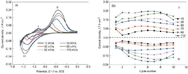
圖10a給出了NP-Fe-Si-B-P在不同掃描速率下的CV曲線,所有的曲線都對應(yīng)第6個電循環(huán)周期
隨著掃描速率的提高氧化峰電位朝正電位方向移動,而還原峰則朝負電位方向移動,表明該電化學(xué)反應(yīng)是一種準可逆的氧化還原反應(yīng)
隨著掃描速率的提高氧化峰Ⅱ和還原峰Ⅲ的峰值電流密度持續(xù)增大
圖10b給出了NP FeSiBP在不同掃描速率下峰值電流密度的變化
可以看出,在電化學(xué)循環(huán)的前幾個周期內(nèi)氧化峰的峰值電流密度持續(xù)增大,然后隨著循環(huán)次數(shù)的增加而逐漸減小
圖10
圖10脫合金處理Fe76Si9B10P5合金在6 mol/L的 KOH溶液中的CV曲線和在不同掃描速率下氧化峰/還原峰的峰值電流密度的變化
Fig.10CV curves of dealloyed Fe76Si9B10P5 alloy in 6 mol/L KOH solution (a) and the change of the peak current densities of oxidation and reduction (b) at different scanning rates
以上數(shù)據(jù)表明,AM FeSiBP的峰值電流密度在第一次循環(huán)時相對較小,但是隨著循環(huán)次數(shù)的增加而增大,這可能是活性部位數(shù)量增加產(chǎn)生的氧化物造成的[34]
與AM FeSiBP不同,NP FeSiBP的峰值電流密度先減小再增大,并在最后幾個循環(huán)中持續(xù)減小
與所有堿性溶液中Fe的循環(huán)極化相同,NP FeSiBP的氧化反應(yīng)可分為兩個步驟:在較低電位E=-1.07 V時Fe→Fe(OH)2,在較高電位E=-0.60 V時Fe(OH)2→FeOOH[35]
這些反應(yīng)物將部分孔隙覆蓋,如圖11所示,在樣品表面的一些片狀產(chǎn)物使納米多孔結(jié)構(gòu)部分被覆蓋或坍塌,從而使比表面積和反應(yīng)活性位點的數(shù)量減小[36],即隨著循環(huán)周期的增加其活性有所降低
圖11
圖11脫合金處理的Fe76Si9B10P5合金在CV測試后的SEM照片
Fig.11SEM morphology of dealloyed Fe76Si9B10P5 alloy after the measurement of cyclic voltammogram
如上所述,F(xiàn)e76Si9B10P5非晶合金在高于773 K的溫度熱處理后結(jié)晶形成α-Fe相、Fe2B相和Fe3P相
圖12給出了熱處理后FeSiBP非晶合金脫合金機理的示意圖
在H2SO4溶液中α-Fe相部分優(yōu)先溶解形成納米多孔結(jié)構(gòu),不同相之間電位差導(dǎo)致形成微電偶,α-Fe晶粒作為陽極發(fā)生優(yōu)先溶解,而相對穩(wěn)定的Fe2B相和Fe3P相則作為陰極殘留下來[37]
這表明,α-Fe晶粒一旦暴露在H2SO4溶液中就迅速發(fā)生選擇性溶解,而具有較高穩(wěn)定性的殘余相Fe2B相和Fe3P相則緩慢溶解
同時,在773 K熱處理且具有納米多孔結(jié)構(gòu)的Fe76Si9B10P5合金表現(xiàn)出比Fe76Si9B10P5非晶合金更高的催化活性,因為多孔結(jié)構(gòu)具有更大的比表面積[38],可以提供大量有利于氧化還原反應(yīng)的吸附點、催化點和大量的反應(yīng)界面
圖12
圖12熱處理Fe-Si-B-P合金脫合金的機制示意圖
Fig.12Diagram of the mechanism of dealloying of annealed Fe-Si-B-P alloys
3 結(jié)論
Fe76Si9B10P5非晶合金在773~833 K熱處理時發(fā)生晶化生成了α-Fe相、Fe2B相和Fe3P相,在酸性溶液脫合金處理過程中α-Fe晶粒優(yōu)先溶解導(dǎo)致納米多孔結(jié)構(gòu)的形成
隨著熱處理溫度的提高,納米多孔的孔徑增大
與原始Fe76Si9B10P5非晶合金相比,熱處理Fe76Si9B10P5合金在脫合金處理后具有更大的活性表面積、更高的孔隙率和更豐富的多孔結(jié)構(gòu),能提供更多的催化位點而使其具有更高的電化學(xué)催化活性
參考文獻
View Option 原文順序文獻年度倒序文中引用次數(shù)倒序被引期刊影響因子
[1]
Liu N, Zhai Z H, Yu B, et al.
Bifunctional nanoporous ruthenium-nickel alloy nanowire electrocatalysts towards oxygen/hydrogen evolution reaction
[J]. Int. J. Hydrog. Energy, 2022, 47(73): 31330
DOIURL [本文引用: 1]
[2]
Tang W G, Zhu S L, Jiang H, et al.
Self-supporting nanoporous CoMoP electrocatalyst for hydrogen evolution reaction in alkaline solution
[J]. J. Colloid Interface Sci., 2022, 625: 606
DOIURL [本文引用: 1]
[3]
Yong Y L, Zhang W J, Hou Q H, et al.
Highly sensitive and selective gas sensors based on nanoporous CN monolayer for reusable detection of NO, H2S and NH3: A first-principles study
[J]. Appl. Surf. Sci., 2022, 606: 154806
DOIURL [本文引用: 1]
[4]
Zheng X H, Qiao X F, Luo F Y, et al.
Low-cost high-performance NO2 sensor based on nanoporous indium tin oxide (ITO) film
[J]. Sens. Actuators., 2021, 346B: 130440
[5]
Yao L J, Li Y X, Ran Y, et al.
Construction of novel Pd-SnO2 composite nanoporous structure as a high-response sensor for methane gas
[J]. J. Alloys Compd., 2020, 826: 154063
DOIURL [本文引用: 1]
[6]
Mohajer F, Ziarani G M, Badiei A, et al.
Functionalized silica nanoporous Pd complex for reduction of nitroarenes and dyes
[J]. Inorg. Chem. Commun., 2022, 144: 109936
DOIURL [本文引用: 1]
[7]
Lahiri S K, Zhang C, Sillanp?? M, et al.
Nanoporous NiO@SiO2 photo-catalyst prepared by ion-exchange method for fast elimination of reactive dyes from wastewater
[J]. Mater. Today Chem., 2022, 23: 100677
[本文引用: 1]
[8]
Ye Z D, Miao R, Miao F J, et al.
3D nanoporous core-shell ZnO@Co3O4 electrode materials for high-performance supercapacitors and nonenzymatic glucose sensors
[J]. J. Electroanal. Chem., 2021, 903: 115766
DOIURL [本文引用: 1]
[9]
Shen W N, Dunn B, Moore C D, et al.
Synthesis of nanoporous bismuth films by liquid-phase deposition
[J]. J. Mater. Chem., 2000, 10A(3) : 657
[本文引用: 1]
[10]
Luo H M, Sun L, Lu Y F, et al.
Electrodeposition of mesoporous semimetal and magnetic metal films from lyotropic liquid crystalline phases
[J]. Langmuir, 2004, 20(23): 10218
PMID [本文引用: 1] " />
A cementation-like process taking place under potential control and introduced in this work as a "potential-controlled displacement" (PCD) is developed as a new method for processing of nanoporous Ag structures with controlled roughness (porosity) length scales. Most of the development work is done in a deoxygenated electrolyte containing 1 x 10(-3) M AgClO(4 )+ 5 x 10(-2) M CuSO(4) + 1 x 10(-1) M HClO(4) using a copper rotating disk electrode at 50 rpm. At this electrolyte concentration, the Ag deposition is under diffusion limitations whereas the Cu dissolution displays a typical Butler-Volmer anodic behavior. Thus, a careful choice of the operational current density enables strict control of the ratio between the dissolving and depositing metals as ascertained independently by atomic absorption spectrometry (AAS). The roughness length scale of the resulting surfaces is controlled by a careful selection of the current density applied. The highest surface area and finest morphology is obtained when the atomic ratio of Ag deposition and Cu dissolution becomes 1:1. Preseeding of uniform Ag clusters on the Cu surface made by pulse plating of Ag along with complementary plating and stripping of Pb monolayer is found to yield finer length scale resulting in up to a 67% higher surface area. An electrochemical technique using as a reference value the charge of an underpotentially deposited Pb layer on a flat Ag surface is used for measuring the real surface area. Scanning electron microscopy (SEM) studies are conducted to examine and characterize the deposit morphology of Ag grown by PCD on Cu substrates.
[19]
Yeh F H, Tai C C, Huang J F, et al.
Sun. Formation of porous silver by electrochemical alloying/dealloying in a water-insensitive zinc chloride-1-ethyl-3-methyl imidazolium chloride ionic liquid
[J]. J. Phys. Chem., 2006, 110B(11) : 5215
[本文引用: 1]
[20]
Yi Q F, Huang W, Liu X P, et al.
Electroactivity of titanium-supported nanoporous Pd-Pt catalysts towards formic acid oxidation
[J]. J. Electroanal. Chem., 2008, 619-620: 197
DOIURL [本文引用: 1]
[21]
Lu H B, Li Y, Wang F H.
Synthesis of porous copper from nanocrystalline two-phase Cu-Zr film by dealloying
[J]. Scr. Mater., 2007, 56(2): 165
DOIURL [本文引用: 1]
[22]
Chang J K, Hsu S H, Sun I W, et al.
Formation of nanoporous nickel by selective anodic etching of the nobler copper component from electrodeposited nickel-copper alloys
[J]. J. Phys. Chem., 2008, 112C(5) : 1371
[本文引用: 1]
[23]
Fukumizu T, Kotani F, Yoshida A, et al.
Electrochemical formation of porous nickel in zinc chloride-alkali chloride melts
[J]. J. Electrochem. Soc., 2006, 153(9): C629
DOIURL [本文引用: 1]
[24]
Qi Z, Zhao C C, Wang X G, et al.
Formation and characterization of monolithic nanoporous copper by chemical dealloying of Al-Cu alloys
[J]. J. Phys. Chem., 2009, 113C(16) : 6694
[本文引用: 1]
[25]
Jia F L, Yu C F, Deng K J, et al.
Nanoporous metal (Cu, Ag, Au) films with high surface area: general fabrication and preliminary electrochemical performance
[J]. J. Phys. Chem., 2007, 111C(24) : 8424
[本文引用: 1]
[26]
Dan Z H, Qin F X, Sugawara Y, et al.
Fabrication of nanoporous copper by dealloying amorphous binary Ti-Cu alloys in hydrofluoric acid solutions
[J]. Intermetallics, 2012, 29: 14
DOIURL [本文引用: 1]
[27]
Xu C X, Liu Y Q, Wang J P, et al.
Fabrication of nanoporous Cu-Pt(Pd) core/shell structure by galvanic replacement and its application in electrocatalysis
[J]. ACS Appl. Mater. Interfaces, 2011, 3(12): 4626
DOIURL [本文引用: 1]
[28]
Ou S L, Ma D G, Li Y H, et al.
Fabrication and electrocatalytic properties of ferromagnetic nanoporous PtFe by dealloying an amorphous Fe60Pt10B30 alloy
[J]. J. Alloys Compd., 2017, 706: 215
DOIURL [本文引用: 1]
[29]
Chen F, Zhou Y, Chen Y N, et al.
Fabrication of nano-porous Co by dealloying for supercapacitor and azo-dye degradation
[J]. Chin. J. Mater. Res., 2020, 34(12): 905
陳 峰, 周 洋, 陳彥南 等.
脫合金制備納米多孔Co及其超級電容器和對偶氮染料的降解性能
[J]. 材料研究學(xué)報, 2020, 34(12): 905
[30]
Ma D G, Wang Y M, Li Y H, et al.
Structure and properties of nanoporous FePt fabricated by dealloying a melt-spun Fe60Pt20B20 alloy and subsequent annealing
[J]. J. Mater. Sci. Technol., 2020, 36: 128
DOIURL
[31]
Chi Y C, Chen F, Wang H N, et al.
Highly efficient degradation of acid orange II on a defect-enriched Fe-based nanoporous electrode by the pulsed square-wave method
[J]. J. Mater. Sci. Technol., 2021, 92: 40
DOI [本文引用: 1] " />
Zinc-air is a century-old battery technology but has attracted revived interest recently. With larger storage capacity at a fraction of the cost compared to lithium-ion, zinc-air batteries clearly represent one of the most viable future options to powering electric vehicles. However, some technical problems associated with them have yet to be resolved. In this review, we present the fundamentals, challenges and latest exciting advances related to zinc-air research. Detailed discussion will be organized around the individual components of the system - from zinc electrodes, electrolytes, and separators to air electrodes and oxygen electrocatalysts in sequential order for both primary and electrically/mechanically rechargeable types. The detrimental effect of CO2 on battery performance is also emphasized, and possible solutions summarized. Finally, other metal-air batteries are briefly overviewed and compared in favor of zinc-air.
[34]
Hu Y C, Wang Y Z, Su R, et al.
A highly efficient and self-stabilizing metallic-glass catalyst for electrochemical hydrogen generation
[J]. Adv. Mater., 2016, 28: 10293
DOIURL [本文引用: 1]
[35]
?erny J, Micka K.
Voltammetric study of an iron electrode in alkaline electrolytes
[J]. J. Power Sources, 1989, 25(2): 111
DOIURL [本文引用: 1]
[36]
Fu C Q, Xu L J, Dan Z H, et al.
Annealing effect of amorphous Fe-Si-B-P-Cu precursors on microstructural evolution and Redox behavior of nanoporous counterparts
[J]. J. Alloys Compd., 2017, 726: 810
DOIURL [本文引用: 1]
[37]
Dan Z H, Qin F X, Zhang Y, et al.
Mechanism of active dissolution of nanocrystalline Fe-Si-B-P-Cu soft magnetic alloys
[J]. Mater. Charact., 2016, 121: 9
DOIURL [本文引用: 1]
[38]
Liu P S.
Calculation method for the specific surface area of porous metals
[J]. Chin. J. Mater. Res., 2009, 23(4): 415
[本文引用: 1]
劉培生.
多孔金屬比表面積的計算方法
[J]. 材料研究學(xué)報, 2009, 23(4): 415
[本文引用: 1] class="outline_tb" " />
Mesoporous semimetal bismuth film and magnetic metal nickel and cobalt thin films have been electrodeposited from hexagonal or lamellar structured lyotropic liquid crystalline phases with polyoxyethylene surfactant. The liquid crystalline templates are characterized by low-angle X-ray diffraction (XRD) and polarized-light optical microscopy (POM). The metal films are characterized by low-angle and wide-angle XRD, scanning electron microscopy (SEM), and transmission electron microscopy (TEM). The magnetic measurements on the mesoporous nickel and cobalt films are shown to have higher coercivity (Hc) than the nonporous polycrystalline films.
[11]
Snyder J, Livi K, Erlebacher J.
Dealloying silver/gold alloys in neutral silver nitrate solution: porosity evolution, surface composition, and surface oxides
[J]. J. Electrochem. Soc., 2008, 155(8): C464
[12]
Dong H, Cao X D.
Nanoporous gold thin film: fabrication, structure evolution, and electrocatalytic activity
[J]. J. Phys. Chem., 2009, 113C(2) : 603
[13]
Wierzbicka E, Sulka G D.
Nanoporous spongelike Au-Ag films for electrochemical epinephrine sensing
[J]. J. Electroanal. Chem., 2016, 762: 43
[14]
Hu L W, Liu X, Le G M, et al.
Morphology evolution and SERS activity of the nanoporous Au prepared by dealloying sputtered Au-Ag film
[J]. Physica, 2019, 558B: 49
[15]
Liu H T, He P, Li Z Y, et al.
High surface area nanoporous platinum: facile fabrication and electrocatalytic activity
[J]. Nanotechnology, 2006, 17(9): 2167
[16]
Thorp J C, Sieradzki K, Tang L, et al.
Crozier, A. Misra, M. Nastasi, D. Mitlin, S. T. Picraux. Formation of nanoporous noble metal thin films by electrochemical dealloying of Pt x Si1- x
[J]. Appl. Phys. Lett., 2006, 88(3): 033110
[17]
Zhang X L, Li G J, Duan D, et al.
Formation and control of nanoporous Pt ribbons by two-step dealloying for methanol electro-oxidation
[J]. Corros. Sci., 2018, 135: 57
[18]
Viyannalage L T, Liu Y, Dimitrov N.
Processing of nanoporous Ag layers by potential-controlled displacement (PCD) of Cu
[J]. Langmuir, 2008, 24(15): 8332
PMID " />
The degradation of acid orange II (AO II) by a nanoporous Fe-Si-B (NP-FeSiB) electrode under the pulsed square-wave potential has been investigated in this research. Defect-enriched NP-FeSiB electrode was fabricated through dealloying of annealed Fe76Si9B15 amorphous ribbons. The results of UV-vis spectra and FTIR indicated that AO II solution was degraded efficiently into unharmful molecules H2O and CO2 on NP-FeSiB electrode within 5 mins under the square-wave potential of ±1.5 V. The degradation efficiency of the NP-FeSiB electrode remains 98.9% even after 5-time recycling. The large amount of active surface area of the nanoporous FeSiB electrode with lattice disorders and stacking faults, and alternate electrochemical redox reactions were mainly responsible for the excellent degradation performance of the NP-FeSiB electrode. The electrochemical pulsed square-wave process accelerated the redox of Fe element in Fe-based nanoporous electrode and promoted the generation of hydroxyl radicals (?OH) with strong oxidizability as predominant oxidants for the degradation of azo dye molecules, which was not only beneficial to improving the catalytic degradation activity, but also beneficial to enhancing the reusability of the nanoporous electrode. This work provides a highly possibility to efficiently degrade azo dyes and broadens the application fields of nanoporous metals.
[32]
Yu F, Zhou H Q, Zhu Z, et al.
Three-dimensional nanoporous iron nitride film as an efficient electrocatalyst for water oxidation
[J]. ACS Catal., 2017, 7: 2052
[33]
Li Y G, Dai H J.
Recent advances in zinc-air batteries
[J]. Chem. Soc. Rev., 2014, 43(15): 5257
PMID [本文引用: 2] " />
提出了一種根據(jù)泡沫金屬的孔率和孔徑這兩個基本參量計算其比表面積的方法. 利用泡沫金屬比表面積與孔率和孔徑的對應(yīng)數(shù)理關(guān)系, 結(jié)合有關(guān)實驗數(shù)據(jù),成功地計算出了電沉積法和高壓滲流鑄造法制備的泡沫金屬的比表面積.
Bifunctional nanoporous ruthenium-nickel alloy nanowire electrocatalysts towards oxygen/hydrogen evolution reaction
1
2022
聲明:
“納米多孔Fe-Si-B-P的脫合金制備及其電化學(xué)性能” 該技術(shù)專利(論文)所有權(quán)利歸屬于技術(shù)(論文)所有人。僅供學(xué)習(xí)研究,如用于商業(yè)用途,請聯(lián)系該技術(shù)所有人。
我是此專利(論文)的發(fā)明人(作者)